
This page is supposed to stand in as a user manual for this device until I can lay my hands on a real manual. It is likely incomplete and some terms have been invented.
The device
The device has a screen and three buttons. Arranged top to bottom with buttons on the right and the display upright the buttons are named in this document as “NEXT”, “SELECT” and “MENU”.
The default display shows the alert mode of the device, a menu for selecting alert modes, the number of pages on the device(?), the current time, the current alert mode, and potentially a list of status icons along the bottom of the screen. Status icons will be described in their relevant sections.
There is a speaker at the far left of the device and an red LED between the main display and the buttons.
Setup
Installing a battery
Setting the time and date
Backlight
Hold the MENU button for several seconds to turn on a backlight. The light will timeout shortly before the screen goes blank.
Alert Modes
On the default display, the available alert modes are shown in the top right corner, with the current mode underlined and also displayed immediately underneath.
The modes in order from left to right are STANDBY, AUDIBLE, DISPLAY and VIBRATE.
Pressing the NEXT button will move the underline to the next mode to the right until at the end it loops back to the start. Either pressing the SELECT button or waiting a moment will cause the underlined mode to be selected. STANDBY and DISPLAY modes will request confirmation.
STANDBY mode. I don’t know what this mode does. I suspect it suppresses any notification of an incoming message
AUDIBLE mode. I don’t know what this mode does. I suspect it causes an audible notification of an incoming message
DISPLAY mode. I don’t know what this mode does. I suspect it causes a visible notification of an incoming message
VIBRATE mode. I don’t know what this mode does. I suspect it causes the device to vibrate on an incoming message
The Main Menu
Press the MENU button to open the main menu. The menu options are MESSAGES, ALARMS, MELODIES, CLOCKS, CONTRAST and QUIT.
Use the NEXT button to select the desired menu item and press SELECT to enter that menu. Either select QUIT or press the MENU button again to return to the default display.
Messages menu
There are three messages folders: Personal, Service 1 and Service 2. I assume messages directed to the pager CAP code go in Personal and there are two broadcast CAP codes in the device for Service 1 and Service 2 messages. Whether these are simply additional notifications or can provide system values such as over-the-air time settings is not known.
Use the NEXT button to select the desired folder and SELECT to enter it, or select QUIT to return to the main menu.
Press MENU to return to the default screen.
Pressing SELECT on the default screen will jump immediately to the Personal Messages folder
Alarms menu
There are four programmable alarms. The first option selects whether the alarm is a one-off or repeats
For one-off alarms, the next item is the date. Use the NEXT button to select the field to adjust and the SELECT button to increment it.
For repeat alarms the next item is the days it should repeat on. Use the NEXT button to select the field to adjust and the SELECT button to increment it. If the days selected span the whole week then it becomes a daily alarm. If the same day is selected on both fields it becomes a weekly alarm. Other options will make the alarm sound between the days, including the named days.
The next field is the time for the alarm. Use the NEXT button to choose a field to adjust and the SELECT button to increment it.
The next field is whether the alarm is active or not. Use the NEXT button to choose it and the SELECT button to switch between on and off.
If any alarms are active then a BELL notification will be displayed in the status icons on the default display.
Melodies menu
Lets you select an individual melody for each inbound message type from Personal, Service 1 and Service 2.
Clocks menu
The menu options are Time, date, Auto 1 and Auto 2. Time and date are self explanatory. Auto 1 and Auto 2 can be used to change the alert mode on a defined schedule. When an auto alert mode is pending, a clock will appear in the status icons on the default screen.
Contrast menu
The contrast options are DOWN, UP and QUIT.
To lighten the contrast, select DOWN with the NEXT button and hold the SELECT button until the desired contrast is reached.
To darken the contrast, select UP with the NEXT button and hold the SELECT button until the desired contrast is reached.
The device will beep and flash if the maximum contrast limit is reached.
Unknown status icons
Icons that I haven’t managed to activate yet are and envelope, a globe, an exclamation mark, a phone, a lock, a folder, a crossed out antenna and an empty battery.
The crossed out antenna might be for making the pager alert that it is out of service range.
The empty battery is probably indicating the installed battery is flat.
Desired features I’ve not found yet
Ideally some secret combination of buttons will reveal the CAP codes for the three message folders and even let the user set it. So far undiscovered.
It’s likely the pager doesn’t know what frequency it is tuned to so can’t display it.
Opening the device
Slide the battery cover latch to the open position and remove the battery cover and battery
Unscrew the screw holding the clip attachment point
Inside the battery case are two clips that hold the case together. Gently insert a pry to open them and prise the case apart from the end the screw was removed from
The circuitboard comes in two modules, the top layer seems to be the pager. The bottom layer then is probably a logic board for the UI stuff. The radio has four trimmer screws on the upper side and several test points.
The pager board can be easily removed from the logic board
Chips
UAA2082H is a POCSAG pager receiver chip. Datasheet here. https://pdf1.alldatasheet.com/datasheet-pdf/view/19816/PHILIPS/UAA2082H.html. Later referred to as The Radio.
PCD5002H is a POCSAG decoder. Datasheet here: https://pdf1.alldatasheet.com/datasheet-pdf/view/18152/PHILIPS/PCD5002H.html. Later referred to as The Decoder.
The Board
Results from probing the test points, left to right. Probe ‘earthed’ to the negative terminal on the battery
Point 1: Pin 6, IF test point; Q channel, on the UAA2082
Point 2: Pin 5, IF test point; I channel, on the UAA2082
Point 3: Ground
Point 4: High. Pin 4 on the connector to the base, assuming the marked pins are 1, 2 and 3.
Point 5: Pin 25, Receiver oscillator enable output, on the PCD5002H POCSAG decoder.
Point 6: Pin 23, Received Data Input, on the PCD5002H POCSAG decoder.
Point 7: Pin 24, Receiver circuit enable output, on the PCD5002H POCSAG decoder.
The Radio
The radio is a UAA2082H pager receiver chip. Datasheet here. https://pdf1.alldatasheet.com/datasheet-pdf/view/19816/PHILIPS/UAA2082H.html
The RF input shown in the data sheet includes an LC band pass filter. Not found it on the board yet, but that’s a work in progress.
The gyrator filter cut-off frequencies are set via resistor R2 between pins 22 (RGYR) and 21 (COM), which in this board is 56.2kOhm, compared to a 47kOhm resistor described in the data sheet. We have yet to find out what this means in terms of frequency. Test points 1 and 2 make the outputs of these filters available and will be indispensable for retuning work later.
The frequency multiplier is controlled by a resistor between pin 26 (RMUL) and ground. In this board, 3.1kOhm. In the data sheet, 2.2kOhm seems to correlate with a *3 multiplier, 1.2kOhm with a *6 multiplier.
The crystal
Removing the radio module shows a foam pad protecting the crystal and another component. The crystal is labelled 153.2250, which is not a listed pager frequency.
Two of the legs of the crystal appear to be linked to ground. The other is linked to the green variable component. That would suggest it is C16, used for tuning the crystal.
The Decoder
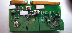
I2C access to the chip can be had (possibly unsafely) by connecting to the resistors shown in the diagram above. The GPIO pins on a Raspberry Pi 2 model B using a python script built on the smbus module works well. TODO: Put on git and provide link.
The I2C lines are provided directly to the other board via the main connector, presumably so the processor on the other board can read the messages. I suspect the main processor isn’t trying to do anything on I2C because the decoder also has an INTerrupt line (pin 5) to notify the processor that there is data to gather.
The data sheet for the PCD5002H decoder explains the BUS ID is 39 and all the registers along with how to access and decode the EEPROM memory.
Disable the decoder via the control register before accessing the EEPROM as the chip will also update indexes as it runs. Turning off the decoder is a requirement to ensure a clear read.
The decoder supports six user assignable codes. Four are set on this device. One is presumably for the personal message folder and two others for the system folders. No idea what the last one is for yet.
